Front Light Guide Plate E-Ink & R-LCD Displays: Technical Deep Dive
A front light guide plate E-Ink and R-LCD displays depend on is the optical component that enables readability in low-light and dark environments. Without it, these reflective technologies, prized for their paper-like readability and ultra-low power consumption, become completely unreadable once ambient light disappears. This guide breaks down how front light guide plates work, what separates a high-performance design from a mediocre one, and what engineers and buyers need to know when evaluating a front LGP solution.
Why the Front Light Guide Plate E-Ink Technology Cannot Do Without
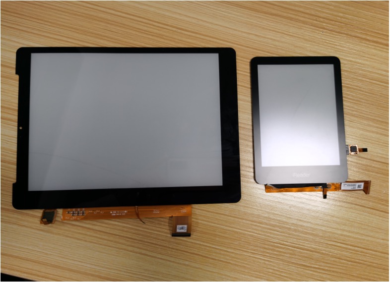
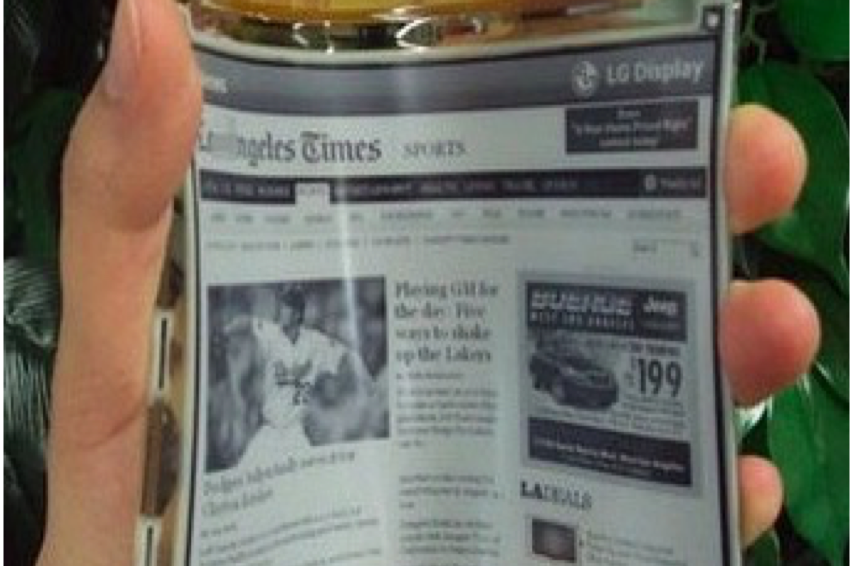
E-Ink and R-LCD displays share a defining characteristic: they rely entirely on ambient light to produce a visible image. Unlike conventional LCD panels that emit light from a backlight module, these reflective technologies bounce incoming light off their surface and back toward the viewer, much like ink on paper.
This is precisely what makes them power-efficient and easy on the eyes. But it creates an obvious problem: in low-light or dark environments, there is no ambient light to reflect, and the display becomes unreadable.
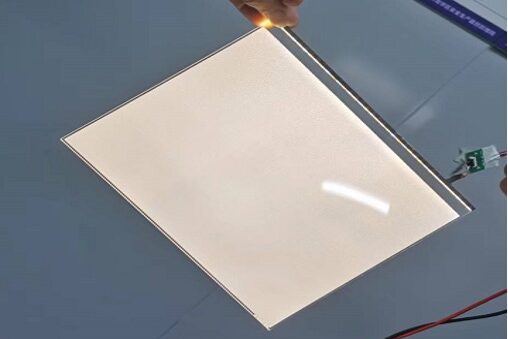
The solution is a front light guide plate, a thin optical film placed in front of the display glass that injects controlled, diffuse illumination directly onto the screen surface when needed, without the power penalty or eye strain of a traditional backlight.
Front Light vs. Backlight LGP: A Critical Architectural Difference
In a standard LCD backlight module, the LGP sits behind the liquid crystal panel. Light travels through the panel toward the viewer. In a front light guide plate module for E-Ink or R-LCD, the LGP sits on top of the display glass. LEDs positioned along one or more edges inject light laterally into the guide. The micro-structured dot pattern etched or stamped into the LGP redirects this edge light downward onto the display, the reflected light then travels back up through the LGP to the viewer.
Key implications of this architecture:
- Bonding method: Front LGPs for E-Ink are typically fully laminated to the display glass using OCA (Optically Clear Adhesive), enabling automation-friendly assembly. R-LCD presents a challenge, its low diffuse reflectance means full OCA bonding significantly reduces brightness. Frame bonding (perimeter only) is typically used instead, though this can introduce a haze effect under certain lighting conditions.
- Eye comfort: Because illumination is diffuse and aligned with the viewer’s line of sight, rather than transmitted directly through the panel, front lighting produces far less flicker and glare, making it well suited for prolonged reading on e-paper displays.
- Typical thickness: Commercial front LGPs range from 0.2 mm to 2.0 mm, with PC (polycarbonate) as the dominant material due to its optical clarity and formability.
Dot Engineering: The Core of Front Light Guide Plate Performance
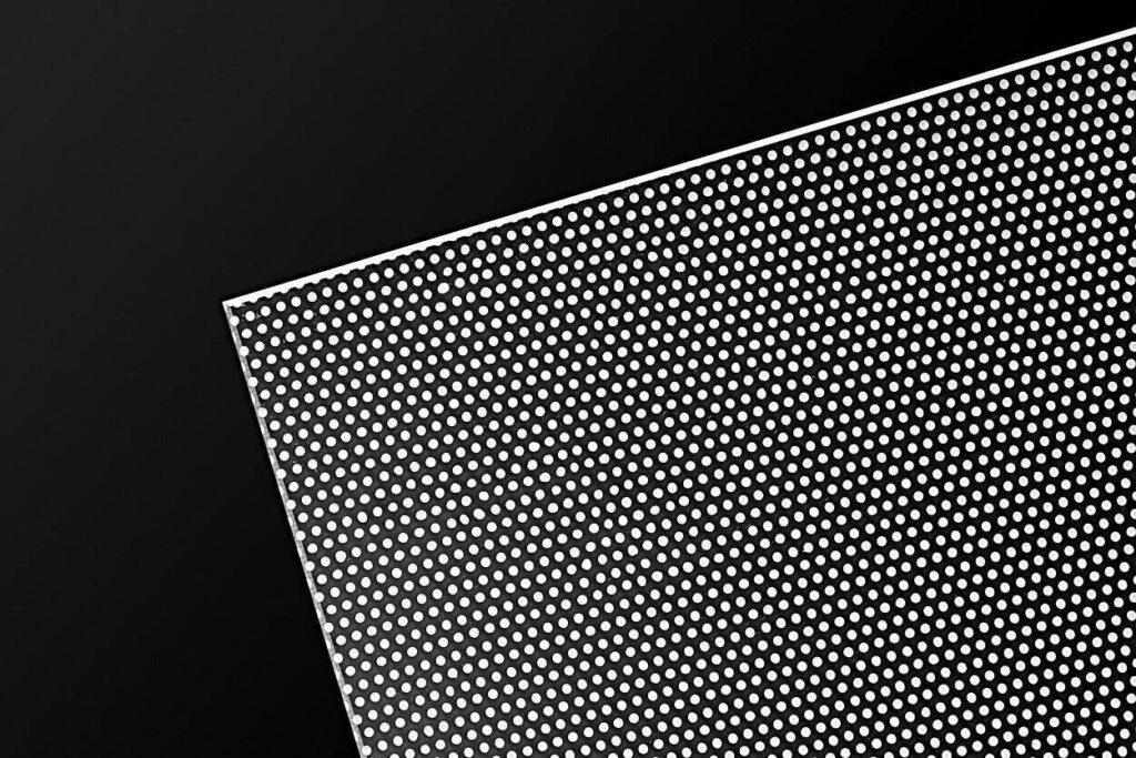
The optical microstructures, commonly called dots, are the heart of any front light guide plate design. Their geometry, depth, diameter, density, and spatial distribution determine virtually every performance metric: brightness, color uniformity, haze, and dot visibility in the final image.
Laser Ablation (Nanosecond & Micro-Laser)
Direct laser ablation is the most widely used dot-formation method in LGP manufacturing. Nanosecond lasers produce a larger thermal-affected zone, creating a crater profile that scatters light broadly, delivering approximately 10% more brightness than micro-laser alternatives. Micro-laser processing uses shorter pulse widths, producing cleaner crater walls with reduced stray light and better color uniformity across the panel. For LED panel backlighting applications that use the same laser-engraving technology, see our Laser LGP series.
Electroforming (Cast Transfer)
Electroforming produces a nickel stamper from a precision master mold. The performance advantages over direct laser are measurable:
| Parameter | Laser Dots | Electroformed Dots |
|---|---|---|
| Diameter | ~37 µm | ~36 µm |
| Depth | ~3.5 µm | ~5 µm |
| Wall profile | Rougher | Smoother, more uniform |
| Color uniformity (ΔE) | >15‰ | <12‰ |
Deeper dots with smoother sidewalls improve light utilization efficiency and reduce visible dot artifacts. Electroformed dots consistently outperform laser dots on color uniformity and haze, two metrics that matter most in high-end e-reader and industrial display applications.
Hot Press Stamping
Used in conjunction with electroformed or CNC-machined molds, roll-to-roll stamping enables high-throughput production of consistent dot patterns at scale, critical for mass-market e-paper display applications.
Next-Generation Front LGP: Shaped High-Brightness Dots
Conventional dot geometries, spherical craters, standard cones, scatter light in all directions. A significant fraction is lost at oblique angles, never reaching the display surface usefully.
Emerging shaped high-brightness dot designs replace rotationally symmetric structures with asymmetric geometries: triangular prisms, crescent forms, and wedge profiles. Rather than scattering, these structures primarily reflect light, concentrating output in the forward direction.
The result is a 5–10% gain in on-axis brightness with no increase in power consumption, a meaningful improvement in applications where every milliwatt counts, such as wearables, e-readers, and always-on signage. Dot diameters are tunable across the 35–60 µm range with pitch spacing optimized per application.
Real-World Optimization: From Front LGP Design to Integrated Panel
Even a well-engineered dot pattern requires tuning once integrated into a real product. Common issues and their solutions:
- Uneven brightness across the panel: Addressed by spatial dot density adjustment, denser dots toward the far edge from the LED source, sparser near the light entry side.
- Dark corners / bright banding: Localized density adjustments in corner and edge zones correct these without affecting overall uniformity.
- LED hot spots / light banding near the entry edge: Serrated microstructures (R-type or V-type, 40–80 µm pitch) introduced at the light entry edge break up the discrete LED pattern before it propagates through the guide.
In-house OCA lamination for sample evaluation significantly shortens the development cycle, optical effect can be confirmed on actual customer display panels before committing to tooling changes.
Front LGP Specifications: What to Look for When Sourcing
When evaluating a front light guide plate supplier for your E-Ink or R-LCD project, these parameters should be part of your qualification checklist:
| Spec | Typical Range | Notes |
|---|---|---|
| Thickness | 0.2 – 2.0 mm | Thinner = more complex optical design |
| Material | PC (polycarbonate) | Best balance of clarity and workability |
| Dot process | Laser / Electroformed / Stamped | Electroformed preferred for color-critical apps |
| Dot diameter | 35 – 60 µm | Smaller = less visible in image |
| Color uniformity (ΔE) | <12‰ | Target for premium displays |
| Light entry | Single / Dual edge | Dual entry improves uniformity on large panels |
| Bonding | OCA full / Frame | E-Ink: OCA; R-LCD: frame bonding preferred |
Frequently Asked Questions About Front Light Guide Plates
What is a front light guide plate?
A front light guide plate (front LGP) is a thin optical film placed on top of a reflective display (such as E-Ink or R-LCD) that redirects LED edge light downward onto the screen surface, enabling readability in dark environments without a power-hungry backlight. For a broader overview of LGP technology and all types, see What Is a Light Guide Plate (LGP)?
Why can’t E-Ink displays use a standard backlight?
E-Ink’s electrophoretic particles are opaque, backlight would simply be blocked. The display must receive light from the front. A front LGP provides this illumination without the glare or power consumption of emissive displays.
What is the difference between OCA bonding and frame bonding for front LGP?
OCA (full-surface) bonding provides the cleanest optical interface and supports automation, and is suitable for E-Ink displays. R-LCD’s low diffuse reflectance means full bonding kills brightness; frame (perimeter) bonding is used instead to preserve light output, though it may introduce slight haze.
How does dot shape affect front LGP brightness?
Conventional spherical dots scatter light isotropically, losing energy at oblique angles. Shaped asymmetric dots (wedge, crescent, prism) reflect light preferentially in the forward direction, improving on-axis brightness by 5–10% with no additional power draw.
Summary
Front light guide plates are a deceptively complex component. The difference between mediocre and excellent performance comes down to dot geometry, manufacturing process control, and the ability to fine-tune density distribution for a specific display’s optical characteristics. As E-Ink and R-LCD adoption grows across e-readers, wearables, signage, and industrial displays, front LGP engineering will remain a critical differentiator in display module performance.
If you are evaluating front light guide plate E-Ink or R-LCD solutions, contact us with your display specifications for a custom optical assessment. For LED panel backlighting, explore our Thin LGP, Diffusive LGP, and Laser LGP series or visit our Custom Projects page for bespoke optical solutions.